Practical Application: Airmovers
The newest edition of the restoration industry’s most critical document, the ANSI/IICRC S500 Standard and Reference Guide for Professional Water Damage Restoration, is here.
With it come several updates, revisions and processes. Some of the most notable include an updated inspection and monitoring section, clarification on the concept of “remediate, then dry” and a consolidated table discussing building materials and assemblies.
Even “Classes of Water” have been dramatically revised for more clarity.
None of the changes in the document, however, have received as much attention as section 13.5.6.1 of the Standard: “Controlling Airflow.”
In this article, we explore the language in this critical section, step by step, and conclude each discussion with a practical approach to application.
After involvement as an IICRC S500 Consensus Body member and careful study of the Standard, the author offers this commentary as his own opinion and not that of the IICRC. The reader is strongly urged to read the ANSI/IICRC S500 2015 in its entirety. This article is intended to help the reader understand the S500, not to replace it.
Continuous airflow across all affected wet surfaces
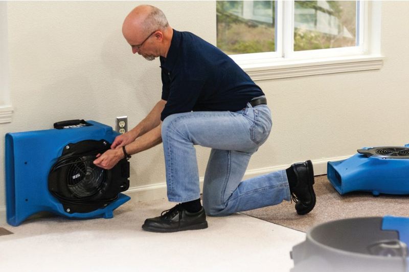
The opening discussion provides several key objectives for airmover installation. In general, the message is to ensure the result is a constant, well-circulated flow of air across all wet surfaces within the drying area. The language notes the need to ensure circulation throughout the environment, address open areas of rooms, account for obstacles, have a concerted focus on lower portions of wet walls and ensure airmovers are moving air in the same direction.
The opening discussion includes the trigger word “should” in regard to “providing airflow across all affected wet surfaces.” The use of this word throughout the document is intentional and has a specific meaning: Where this trigger word is used, it indicates the statement is “a component of the accepted standard of care.”
The language in this section, therefore, provides the restorer with a means to ensure airflow addresses all wet areas, regardless of the circumstances. Because the shape and size of each drying project varies dramatically, there will be circumstances where any formula or other systemized approach will not be adequate: The restorer must simply add another airmover to address hard-to-reach areas.
From a practical standpoint, this means literally feeling for or measuring airflow along wet surfaces, especially in hard to reach areas, and adding or repositioning equipment until every wet surface is in contact with moving air.
Installing airmovers, Plan A: Square foot calculation
The next discussion in section 13.5.6.1 addresses the installation process for airmovers. It is initiated by installing one airmover in each affected room. The restorer is then directed to add airmovers if any of several criteria are met.
These include:
- Adding an airmover for every 50-70 square feet of affected wet floor,
- Adding an airmover for every 100-150 square feet of affected wet wall area above two feet and ceiling surfaces, and
- Adding an airmover for each wall inset or offset greater than 18 inches.
As with the opening section, the language regarding installation is preceded with the trigger “should,” and is thus a component of the accepted standard of care.
Therefore, the method should be used regularly, unless there are circumstances that cause the restorer to do otherwise.
This language is a significant shift from the previous edition of the ANSI/IICRC S500, which provided a guideline for installing airmovers along wet affected walls (every 10-16 linear feet), but no specific criteria for addressing upper walls, ceilings or open floors.
When applying the language from this discussion, it is important to note that one airmover is installed in an affected room first, then airmovers are added to that room for the wet floor area and wet upper wall and ceiling areas.
Installing airmovers, Plan B: Linear foot calculation
Next up in the section is a discussion regarding water migration that has affected a significant length of wall but little to no floor area. This is what restorers may see when water has migrated under and into a wall, but has not traveled far into the adjacent room.
Here, the language reads, “Install a total of one airmover for each 14 affected linear foot of wall.” The linear foot calculation of the previous edition makes the most sense for this specific type of water intrusion, and has thus been retained as a standard for these circumstances.
Apply this method whenever water has affected a significant length of wall but has migrated less than a couple of feet into the room. Keep in mind, however, that based on the circumstances you should choose Plan A or B. The language specifically states that this method is “independent of the above SF calculation, and is not meant to be used in the same room or area.”
Adjust as needed
The final discussion in the airmover language discusses the need to adjust air flow as the job progresses. Here again there are a few statements that contain the trigger word “should.” Generally, the language directs the restorer to monitor and inspect the project daily and adjust the number, type and placement of airmovers as needed. The one specific adjustment discussed relates to projects that meet the criteria of “Class 4 intrusions,” such as projects involving significant water absorption into low-evaporation materials and assemblies. In other words, the difficult stuff.
When you’re up against these hard-to-dry materials and assemblies, the standard directs the restorer to shift focus once surface water has been evaporated, and rely more on vapor pressure differentials as opposed to airflow velocity.
Note that the only trigger in the language, however, is that the restorer “should” increase vapor pressure differentials by lowering the humidity in the air, by warming the wet materials, or both. Reduction of airflow velocity is not indicated as a part of the standard of care, as the trigger language (for example, “should”) is not included with the statement.
A practical system
In summary, here is a practical method for applying this new airmover installation language. After the structure has been prepared for drying (remediation, removal of unrestorable goods and extraction are complete), use the following process in each wet, affected room or area:
Step 1: Install one airmover, directing air into the room from the adjacent affected space. This airmover can draw air from a doorway or opening to the adjacent affected space and blow along either an affected wall assembly or the open floor.
Step 2: Calculate square foot requirements. Divide the wet floor area (square feet) by 50 to get your maximum and by 70 to get your minimum. If walls are wet higher than two feet, or ceilings are wet, then divide the upper wall and ceiling area by 100 to get your maximum, and by 150 for your minimum. Add the flooring numbers to your upper wall and ceiling numbers for your total range. Example:
- a. Floor Area: 140 square foot Wet = Min. 2, Max. 3
- b. Wall/Ceiling: 130 square foot Wet = Min. 1, Max. 2
- c. Total Range: Min. 3, Max. 5
Step 3: Install airmovers. Now that you have your range, start deploying the additional airmovers. Start along the walls, if they are affected, and ensure the entirety of the wet wall and ceiling areas are in contact with moving air. Then, turn your attention to the open areas. Install the remainder to address any floor area that needs additional airflow. Pay special attention to obstructions, offsets or other anomalies that may be restricting or affecting air flow.
Remember, you already needed one airmover (Step 1) because it was a wet room — that airmover is already running. So, for Step 3, install 3-5 additional airmovers in that room. You’ll end up with 4-6 total airmovers installed.
Review: Key concepts for airmover calculations per the S500
During the development and initial review of the ANSI/IICRC S500, misunderstandings arose about several very important components of the airmover installation process. This article addresses these key areas. Because they are critical to accurate application, however, here’s a quick summary:
- Room by room: The method is used on a room-by-room basis. Do not add up the total surface area of the structure, as this will yield an inaccurate result. Do the math for each room or area separately.
- Start with one, then add: The process of installing airmovers in a room is initiated by using one airmover, then adding airmovers for floor, wall and ceiling areas.
- Round up: When a calculation results in a fraction or decimal in any given room or area, round up to a whole number. For example, calculations that result in 1.1, 1.5, or 1.75 should all be rounded up to 2.
- Use wall lengths when appropriate: In cases where there is little wet floor and mostly wet lower wall area, use linear feet of wall (at 1 per 14 feet.)
- Address all wet surfaces: Regardless of what the calculations suggest, all wet areas must have consistent airflow. If the math comes up short and there are wet surfaces with no airflow, add airmovers or adjust their position until airflow is adequate across all wet surfaces.
Brandon Burton is the technical director for Legend Brands, and an instructor with the Restoration Sciences Academy (RSA). He teaches IICRC-approved classes in the categories of Applied Structural Drying (ASD) and Water Damage Restoration (WRT). Burton has served the restoration community for more than 20 years, including 15 as an IICRC-approved instructor, ANSI/IICRC S500 chapter chair, RIA restoration council member and in many other industry roles. You can contact him at BrandonB@RSA-HQ.com.


